Instructions
...
Related articles
| Filter by label (Content by label) | ||||||||||||||||||
|---|---|---|---|---|---|---|---|---|---|---|---|---|---|---|---|---|---|---|
|
...
| hidden | true |
|---|
...
First Release: November 2017 (JD)
Revision A: Replaced link to Fusion part file January 2018 (JD)
Revision B: Full comb through. Updated inaccurate screenshots, changed stock material and size, edited wording, changed V2 to V2-10. February 2019 (QR)
Introduction
The purpose of this tutorial is to demonstrate how to set up a model in Fusion 360, how to program toolpaths, and how to set up and cut the part on your Pocket NC V2-10.
Section 1: Model Setup
When setting up any part on the Pocket NC mill, it is recommended that users include their workholding system (vise, sacrificial plate, ER-40 collet system etc.) in the CAM environment. This will help users visualize the orientation of the part on the machine and avoid collisions.
For this tutorial we will need the B axis table and vise model, download them here. Download the V2 First Part file used in this tutorial here. Choose Fusion 360 Archive as the file type when downloading both models.
...
Because Fusion 360 is cloud based software, users will need to upload both models to Fusion. To do this, first open the data panel.
...
Then select upload and migrate to the file location.
...
Files uploaded to Fusion will stay within the Data Panel and can be accessed any time in the future from that location. Once the files are uploaded, open the Pocket NC table and vise model by double clicking on it or right clicking the file and selecting open.
...
Open the B Table and Vise file. Double check that the B table offset is correct. This point must be the same point in space as the origin/rotation point of your machine.
Measure the distance from the B Table to the end point of the “B Table Offset” sketch as shown in the image below. If the distance does not match the B table offset for your machine, (found in the documents shipped with your machine), edit the sketch so that the endpoint of the line is the correct height above the B table. This point will be the origin point for all of your toolpaths. If this point is not used as the origin point for toolpaths the part will be cut in a different location than expected.
...
...
Section 1.1: Part Geometry
Open the V2 First Part by double clicking on it in the Data Panel. Familiarize yourself with the geometry of the part and try to think about how it will be machined. There a 5 faces that need to be machined, 3 pockets, 1 hole, and a hemisphere and chamfer on the top of the part.
...
...
Note that the pockets and hole on the part are .25 inches deep. This means that the tool used to make this part must have flutes at least .25 inches long or have a reduced shank if it’s flutes are shorter than .25 inches.
...
Open the “sketches” dropdown menu in the model tree. Click on the light bulb icon next to the sketch called “Stock Size” This will open the sketch showing the profile of the stock used to make the part. The stock used for this part is 2 inches on each side.
...
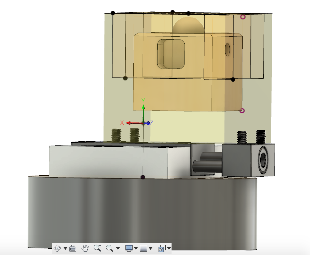
The part is going to be held in the Pocket NC vise. The tool holder has a diameter of about 0.75 inches, this means that nothing can be cut closer to the vise than half of the tool holder diameter, so no lower than .375 inches above the vise. In order to make sure that nothing will crash, we will use bounding boxes to constrain where the tool is allowed to go.
Click on the light bulb icons next to the sketches labeled Bounding Box 1, Bounding Box 2, Bounding Box 3 and Bounding Box 4. To view the bounding boxes that have been set up for this part. Open one of the bounding box sketches and note how the bottom of the box has been set 0.5 inches from the base of the part. This number was chosen because it is half of the tool holder diameter plus the diameter of the tool that will be used.
...
Turn on all 4 of the bounding box sketches and the stock size sketch and save the part (Ctrl+S).
You may now close this file if you would like.
...
Section 1.2: Machining Setup
Open the B-Table and Vise file if it is not already open. Make sure that you are in the “Model” workspace. You should see “Model” in the upper left of the screen as seen in the second picture in page three.
Import the V2 First Part into the setup by right clicking on the “V2 First Part” file in the Data Panel and selecting “Insert into Current Design” from the dropdown menu. Use the “Move” tools that are automatically active to locate the part approximately centered within the vise’s gripper screws. Once the part is roughly aligned, click OK.
...
The first step is to adjust the vise to match how the part will be held. To do this the two screws in the fixed jaw need to be moved, then the part can be aligned with them and the location of the moveable jaw can be adjusted. To move an object in Fusion 360, use the keyboard shortcut “m” or right click in the modeling space and select “move”. Now, choose “components” as the Move Object, “free move” as the move type and select the parts that you want to move.
...
The two set screws in the fixed jaw of the vise will need to be moved as will the moving jaw of the vise. Start by moving the gripper set screws on the fixed jaw (long side of the vise) by selecting both components in the design tree and selecting move. The hole spacing for the grippers is 5mm, so the they will have to move a total Y distance of 20mm to match the picture below. Note that the “V2 First Part” had been hidden in the screenshot below. Move the set screws to the 6th hole in the fixed jaw.
...
Next, locate the V2 First Part so the transparent square representing the stock size overlaps the gripper set screws on the right by about 0.01”. Note, when material is placed in the vise between the grippers, some of the stock material will be crushed. By overlapping material with the grippers, users will get a better representation of what is actually happening on the machine. Move the components so that the set screws on the left have a similar overlap with the stock material to the set screws on the right.
The grippers on the left are mounted to the movable jaw of the vise, this means they can move in any increment. To move the left grippers, open the move tool and select all components in this assembly by clicking on them in the design tree. The whole assembly can now be moved to the desired location.
.
...
The final position of the V2 First Part, relative to the vise and gripper jaws, is shown below.
...
The CAM assembly is almost complete, the last step to locating the V2 First Part is setting the height from the vise. The part will be made from a 2 x 2 x 2 inch stock material and the part is 1.45 inches tall, this means that the base of the part needs to be raised up off the material enough that the user doesn’t have to cut away so much material from the top of the stock. Use the align tool to move the part to a known location (face of the vise). First, select the bottom face of the the part, hold the CTRL key on the keyboard then select the top face of the vise, either the moveable or fixed jaw will work.
...
Right click in the model space and choose “Align” from the menu. The part will be moved so that the bottom face of the cube and the top face of the vise are coplanar.
...
Next, raise the part .5” in the X direction using the move tool. Save your progress.
...
Note- The following screenshots may show the V2 First Part still aligned coplanar with the top of the vise, please disregard. The part should be above the vise like seen in the picture below.
...
Section 2: CAM Settings
To begin making toolpaths for the V2 First Part users must first migrate from the MODEL environment to the CAM environment in Fusion. To do this select the “Change Workspace” drop down tab at the top of the screen, then select Manufacture.
...
Before toolpaths can be created, a Setup must be created that includes origin location, stock material and a coordinate system. To create a Setup select the setup dropdown and “New Setup”.
...
The Setup is a tool for Fusion 360 to understand excess material, objects to avoid and the machine's initial position. To edit a setup, right click on it and select edit.
The first part of a setup is selecting the work origin and orienting the Work Coordinate System (WCS). To set up the WCS within the Fusion CAM environment, select the WCS dropdown and “Select Z axis/plane & X axis” in the “Orientation” field.
...
Two pieces of geometry will need to be selected to complete the “Orientation” field, one for the Z Axis and one for the X Axis. To do this, select the box next to “Z Axis” with a mouse in it, then select geometry (a straight line) on the vise perpendicular to the moveable axis of the jaw and parallel to the work table. Repeat the operation for the X Axis, selecting a feature perpendicular to the work table. When finished users should have a WCS that looks like the image below. If you need to change the directions of the axes, use the “flip _ Axis” check boxes to flip them.
...
The orientation of the B axis is flat or (perpendicular) to the spindle of the Pocket NC when homed. This needs to be reflected by the WCS. On the Pocket NC, the Y Axis moves the table up and down this must be reflected in the setup for the output code to work with the machine. The positive Y direction of the WCS should point straight up from the the B table.
Next, you will select the origin of the machine within the model. The origin of the machine is represented by a point in space about 0.835 inches off the surface of the table at the center of rotation. This point varies slightly from machine to machine and can be changed from the downloaded model to match each specific machine. This should have been done in Section 1.
In the Setup menu change the Origin type to “Selected Point.” Then select the top point of the B table offset sketch.
...
Next, set which parts of the model are going to be machined and which ones are part of the fixture. Click on the “model” selection box then click on the model of the V2 First Part. The selection box should now say “body” or “component”. This will set the cube as the model that will be machined.
...
The portions of the model that we don’t want to be machined should be identified as part of the fixture. Select the checkbox next to the “Fixture” heading. Click the fixture selection box then click on the vise, vise fixture and gripper screws. This completes all of the settings in the first tab of the Setup.
...
Click on the “Stock” tab of the Setup settings window. This is where the size and position of the stock, the block of material out of which the part will be machined, are defined.
First choose “Fixed size box” as the stock mode. This part will be made from a 2 x 2 x 2 inch block of wax so the “Width” “Depth” and “Height” of the stock should all be set to 2 inches. Because the part is centered in the block of stock material no offsets are needed in the X and Z directions. The base of the stock is against the vise so the stock needs to be shifted down 5 inches in the Y direction. To do this, select “Offset from frontside (-Y)” in the “Model Position” field. Then input .5 in the “Offset” field.
The bottom of the stock should now be coplanar with the top of the vise.
...
The “Post Process” tab in the Setup window allows you to change the program number and add comments that will be integrated into the code when it is post processed. Do not edit the WCS offset boxes. The code will not run correctly on the Pocket NC if a WCS offset is set.
...
When finished in the “Post Process” tab, click OK to save and apply all the changes to the Setup you just created. Save your progress.
...
Section 3: Tool Setup
Section 3.1: Importing the Pocket NC Tool Library
The tool used to cut this part is the ⅛ inch single flute cutter that was sent with the Pocket NC. This is tool number 52508. This tool is only suitable for cutting soft material such as most wood, plastic, and machinable wax. Do not use this tool for machining metal or other hard materials. Before users can generate toolpaths to run on the Pocket NC they will need to download and install the Pocket NC Tool library (available below). Click here to watch a screencast of how to do this. Screenshots to illustrate the process are also shown below.
To install the new tool library, select “Manage” then “Tool Library”
...
Next, under “Libraries” select “Local” then “Library”. Now right click on “Library” and select “Import Tool Library” to select the Pocket NC Tool Library from your downloads location.
...
That is all that is needed in this window so you may close it for now.
...
Section 3.2: Physical Tool Setup
In order to cut the part in the way described in this tutorial the ⅛ inch single flute cutter will need to be held in an extended tool holder. The tool will need to stick out of the holder about 1.25 inches as shown in the picture below.
If you are using the cutter that was sent pre installed in a tool holder with your machine, you will need to increase the tool stick-out about 3/4 of an inch in order to make this part. There should be about a three quarters of an inch of the shank of the tool visible sticking out of the collet.
...
Section 4: Adaptive Toolpaths
Adaptive toolpaths will be used to clear the bulk of the material from the top and sides of the part. This type of toolpath tries to minimize the machining time while also lengthening the life of the cutter by taking passes that keep the load on the tool constant.
Section 4.1: Adaptive Toolpath for the Top Face
To create the first toolpath, navigate to the “Manufacture” workspace select 3D > “3D Adaptive Clearing”.
...
First, select the ⅛” single flute cutting tool from the imported Pocket NC Tool Library. This tool is tool 10 in the Pocket NC Tool Library. See Section 3.1 for instructions on how to import this tool library. Click on the “Select” button Use the settings in the picture below to get the correct feeds and speeds for making the cube in wax.
Note - Some of the following photos may show the selected as tool 15, please disregard and use tool 10 as stated above.
...
In the geometry tab, set up the tool orientation so that the coordinate system matches that of the image below. You will need to select the coordinate system by picking the X and Z axes and using the “flip axis” buttons to orient them appropriately.
It is critical to get your toolpath oriented correctly! It must match the picture below exactly.
Also make sure that the toolpath origin is set to match the world coordinate system origin that you defined in the setup. The origin must be set to: “Setup WCS Origin”
Next, click the “Stock Contours” box to check it. Because the stock is square, the toolpath will automatically use the outline of the top of the stock as the boundary for the toolpath. You do not have to select a contour. Click the “Heights” tab to continue.
...
The “Heights” tab is where users will select the depths for machining. For this operation, select the cube top as the “bottom height”. This will be the maximum depth the tool will cut to. “Top Height” should be the top of the stock. This will not need adjusting if the stock is setup properly. In the screenshot below, an offset of 0.02 inches has been added to the top height to account for a slightly oversized piece of stock material. If you are having trouble selecting the top of the block, hover over it then left-click and hold to bring up a menu of options to select.
...
The “Passes” tab controls how much material is removed at any given time. Three values need to be adjusted to get a proper cut; "Optimal Load", "Maximum Roughing Stepdown”, “Fine Stepdown” and "Stock to Leave". The settings below work well for wax, you will probably want to decrease the “Optimal Load” to .05 or less for plastics.
...
Since this is a roughing toolpath you want to leave some of the stock material to be removed by the finish toolpaths that will give a better surface finish. 0.020 inches is a good amount of stock to leave when machining wax. Feel free to experiment to find the best amount of stock to leave for your application. If the surface finish is not important, you could remove all of the stock with roughing toolpaths and skip the finishing toolpaths.
The last tab, "Linking" allows the user to fine tune the behavior of a tool path. For example, "No Engagement Feedrate" can be altered from 20 in/min to 40 in/min to save time when the tool is in a retract and not cutting. And the entrance and exit behavior of the toolpath can be adjusted.
The only settings that have been changed in the screenshot below are decreasing the helix diameter to 0.05 inches and increasing the ramp angle from 2 degrees to 10 degrees. These changes will save time when machinings. The harder the material that is being machined the shallower the ramp angle should be, 2 degrees is good for Aluminum, but 10 - 15 degrees is appropriate for wax.
...
When finished making changes to the toolpath select "OK" to save changes.
Fusion will calculate the toolpath. This may take a few seconds to a minute depending on how fast your computer is and how complex the toolpath is. After the toolpath has been generated, the toolpath will be displayed when you click on it in the design tree.
...
The tool path should look something like the image above removing all material within the boundary. This toolpath can now processed into g-code and sent to the machine. However we will finish up the rest of the toolpaths first before post processing them. See section 9 for directions on how to create G-code from your toolpaths.
...
Section 4.2: Adaptive Toolpaths for the Sides of the Part
The toolpaths used to clear the bulk of the material from the sides of the part can be created quickly by duplicating the adaptive toolpath used to machine the top of the part and making a couple of changes.
Start by right clicking on the first adaptive toolpath, and choose “Duplicate” from the menu. Repeat this operation 4 times, to create the four toolpaths for the sides of the part.
...
Right click on the duplicate copy of the toolpath and select “Edit” to view and edit the toolpath settings.
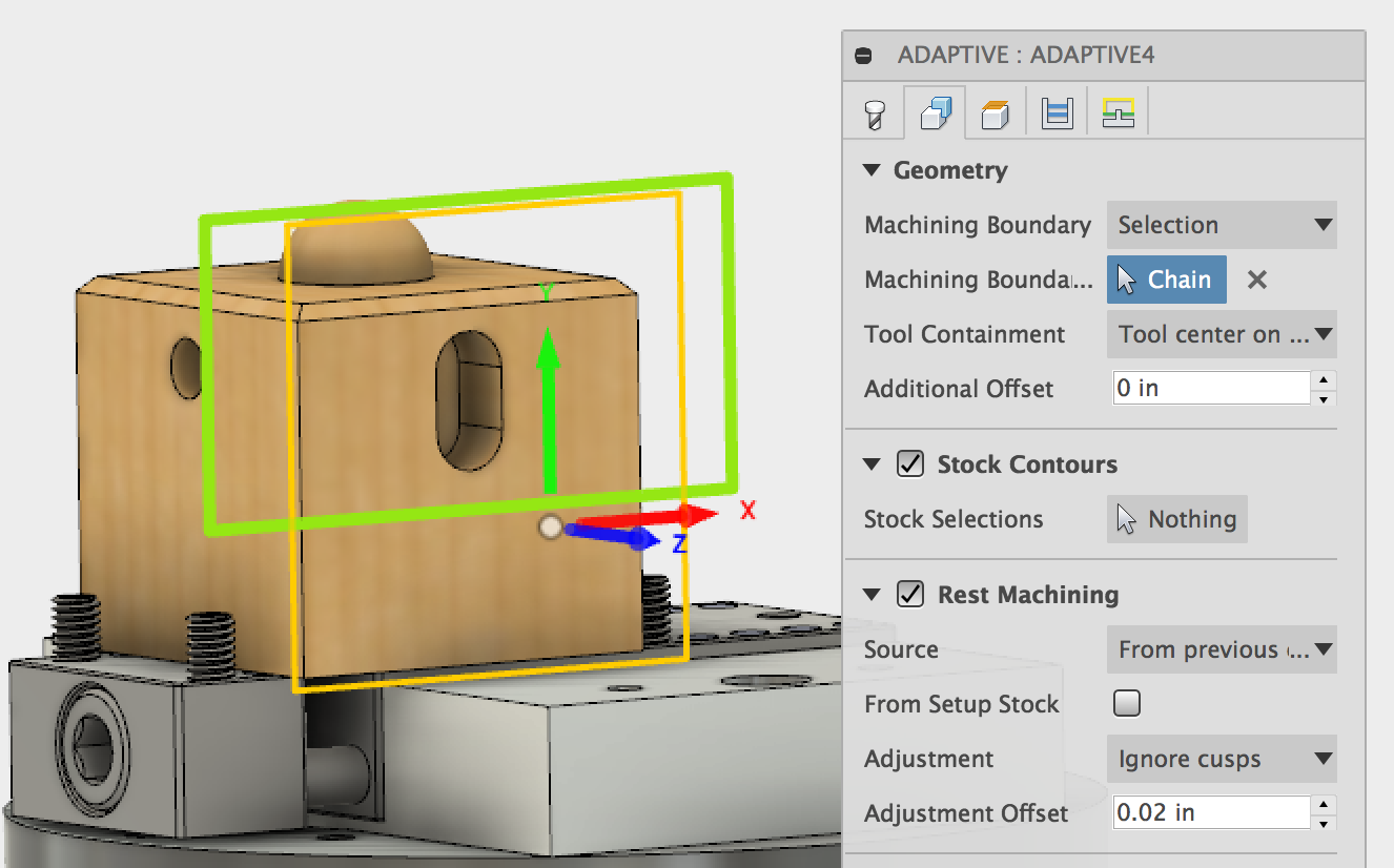
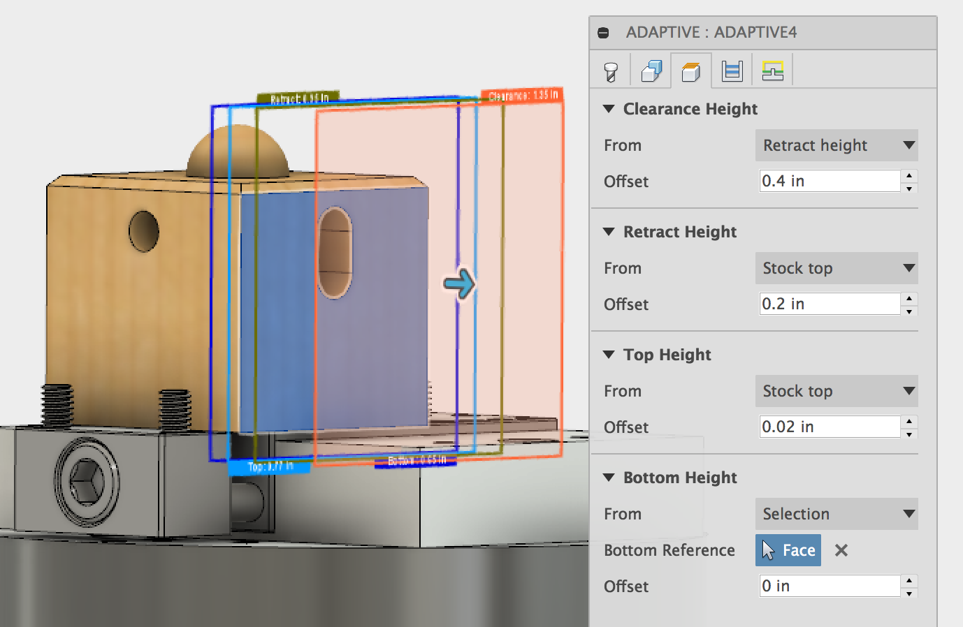
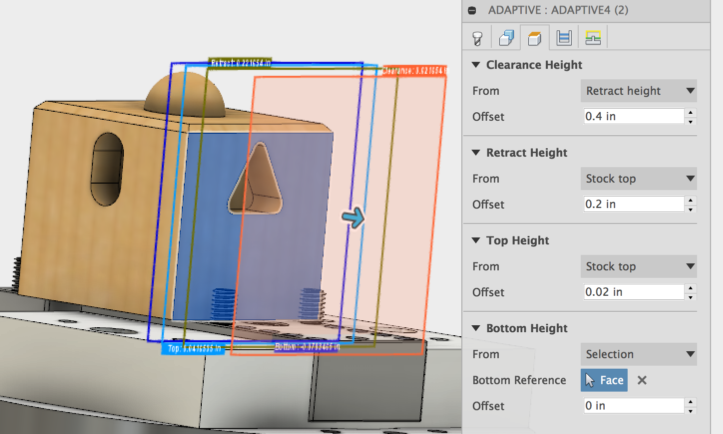
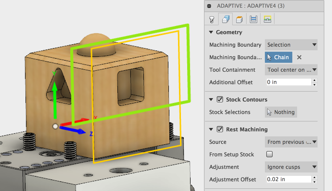
There are four changes that need to be made to the toolpath. First, the orientation of the toolpath must be updated, the bounding box for the toolpath needs to be updated, and the rest machining option needs to be turned on in the “Geometry” tab, then the top face needs to be re-selected in the “Heights” tab. The settings in the “Tools,” “Passes,” and “Linking” tabs can be left alone.
The following screenshots show the changes that need to be made.
...
Select the “Bounding Box 1” sketch as the machining boundary.
The “Rest Machining” button should be selected. Choose “From Previous Operation” as the source. This will keep the software from creating toolpaths that will recut material that has already been removed.
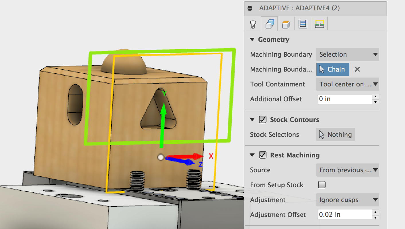
The orientation of the toolpath needs to be changed so that the Z axis points away from the face being machined and the Y axis points toward the top of the part.
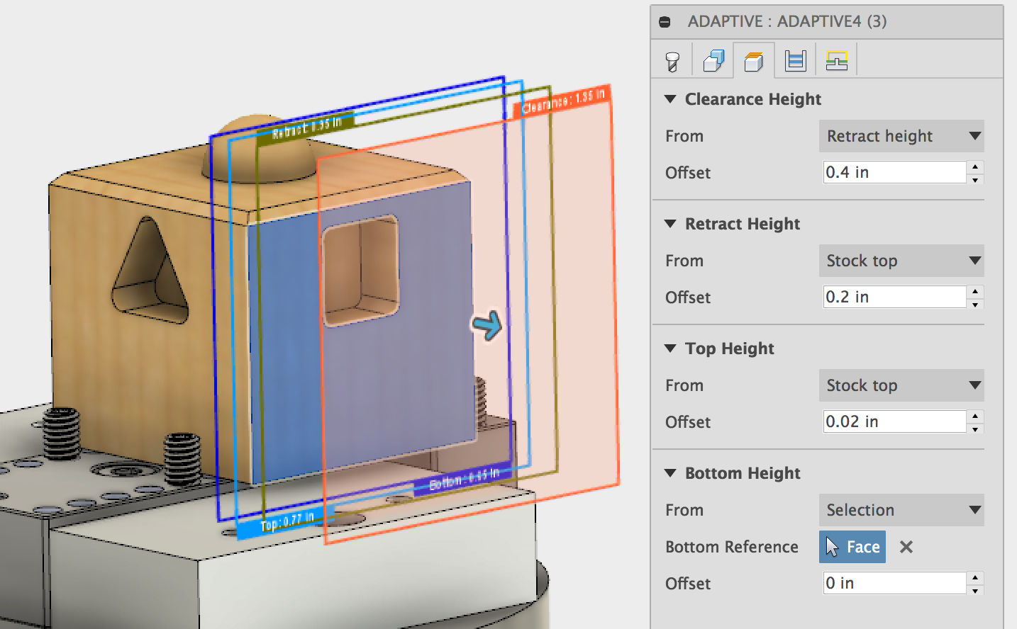
Finally, change the settings in the “Heights” tab to match the screenshot below.
...
Click “OK” to save and apply the changes. Click on the toolpath that you just edited to view it. Make sure that it looks similar to the screenshot below. The path cannot be too close to the vise and gripper screws or else a collision may occur.
...
Repeat these steps for the other three sides of the part. The screenshots below show the orientation of the toolpaths and the height settings. The machining boundaries are the bounding box sketch 2, 3, and 4 respectively.
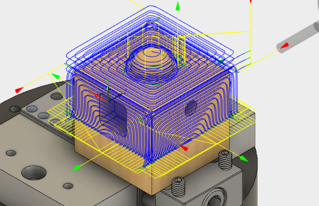
When you are finished with creating the adaptive toolpaths they should look similar to the pictures below. You can view more than one toolpath at once by holding down the “Ctrl” key while selecting them from the model tree. See section 9 for directions on how to create G-code from your toolpaths.
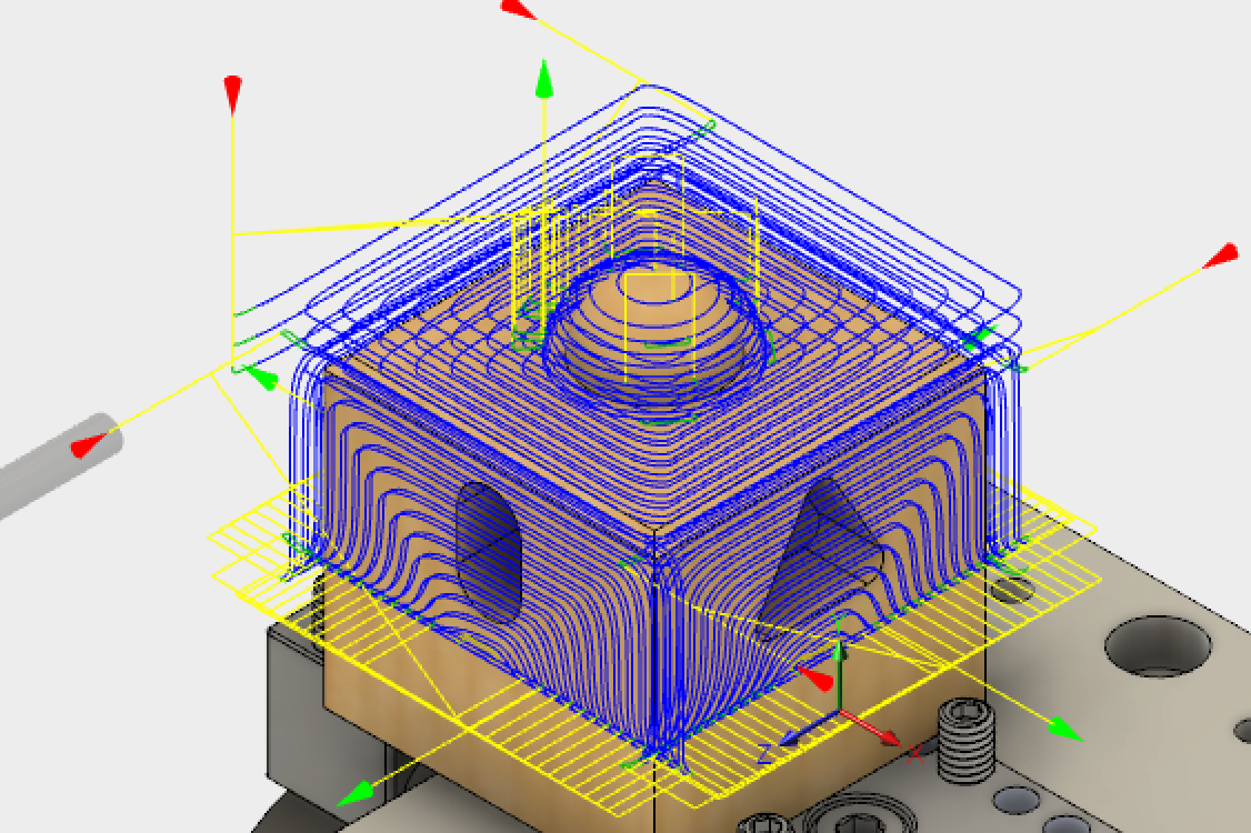
The adaptive toolpaths will remove the bulk of the material from the top and sides of the part as shown in the images below.
...
Section 5: Boring Toolpath
A boring toolpath will be used to create the round hole in the side of the part.
...
An ⅛ inch single flute cutter will be used for this toolpath. This is tool 15 in the Pocket NC tool library. See section 3.1 for instructions on importing the Pocket NC tool library. See section 3.2.1 for instructions on how to select the tool for a toolpath. The speeds shown below work well for wax. They may have to be decreased for harder materials.
...
The settings for the “Geometry” tab are shown below. Select the interior face of the hole as the “Circular Face Selection.” Set the orientation of the toolpath to match the image below. Make sure that the toolpath origin is the “Setup WCS origin.”
...
The settings for the “Heights” tab are shown below. Most of these should be the default settings for the toolpath. Make sure that the top height is set as “Hole Top.” Here, an offset of .01 inches is added to help account for the .02 of material that was left behind by the adaptive toolpath. Make sure that the bottom height is set to “Hole Bottom.”
...
The settings for the “Passes” are shown below. The “Pitch” controls how quickly the tool plunges into the material. The settings shown below are appropriate for wax. They would need to be decreased for harder materials. Click the button to repeat the finishing pass so in order to get a better surface finish.
...
The settings in the “Linking” tab are shown below. The default settings will work.
...
When you are finished editing the toolpath, click “Ok” to close and save the toolpath settings. Fusion will calculate the toolpath. After the toolpath has been calculated it will display when you click on it in the model tree. It should look similar to this. See section 9 for how to create G-code from your toolpath.
...
Section 6: Pocketing Toolpaths
Section 6.1: Toolpath for Slot
Pocketing toolpaths will be used to create the slot, the triangular pocket and the square pocket.
...
The ⅛ inch single flute cutter will be used for these toolpath. This is tool 10 in the Pocket NC tool library. See section 3.1 for instructions on importing the Pocket NC tool library. See section 3.2.1 for instructions on how to select the tool for a toolpath. The speeds shown below work well for wax. They may have to be decreased for harder materials.
...
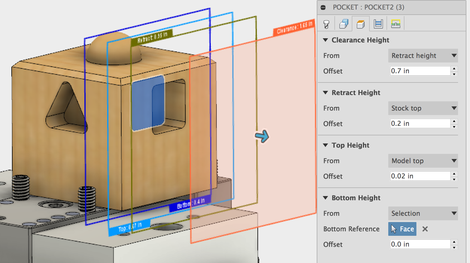
The settings for the “Geometry” tab are shown below. Select the lower profile of the slot at the machining boundary. Select the tool containment method as “tool inside boundary.” Set the orientation of the toolpath to match the image below. Make sure that the toolpath origin is the “Setup WCS origin.” Note that rest machining is off.
...
The settings for the “Heights” tab are shown below. Most of these should be the default settings for the toolpath. Note that the Bottom Height is set as “Selection” with the bottom face of the slot selected.
...
The settings for the “Passes” are shown below. The stepdown and stepover (optimal load) shown below are appropriate for wax. They may need to be decreased for harder materials.
...
The settings in the “Linking” tab are shown below. The default settings will work.
...
When you are finished editing the toolpath, click “Ok” to close and save the toolpath settings. Fusion will calculate the toolpath. After the toolpath has been calculated it will display when you click on it in the model tree. It should look similar to this. See section 9 for details on how to create G-code from your toolpath.
...
Section 6.2: Triangular and Square Pocket Toolpaths
The toolpaths used to create the triangular and square pockets can be created quickly by duplicating the pocketing toolpath used to machine the slot and making a couple of changes.
Start by right clicking on the pocketing toolpath toolpath, and choose “Duplicate” from the menu. Repeat this operation 2 times, to create the two toolpaths for the remaining pockets.
...
Right click on the duplicate copy of the toolpath and select “Edit” to view and edit the toolpath settings.
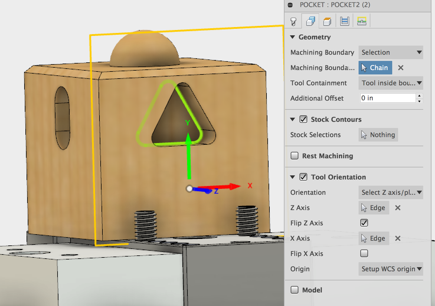
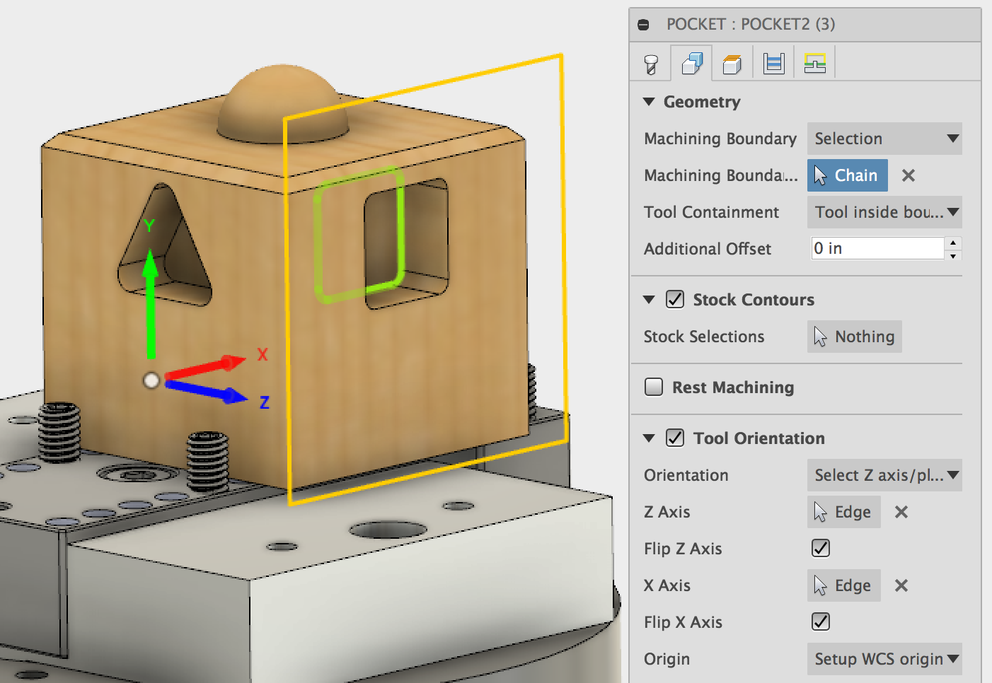
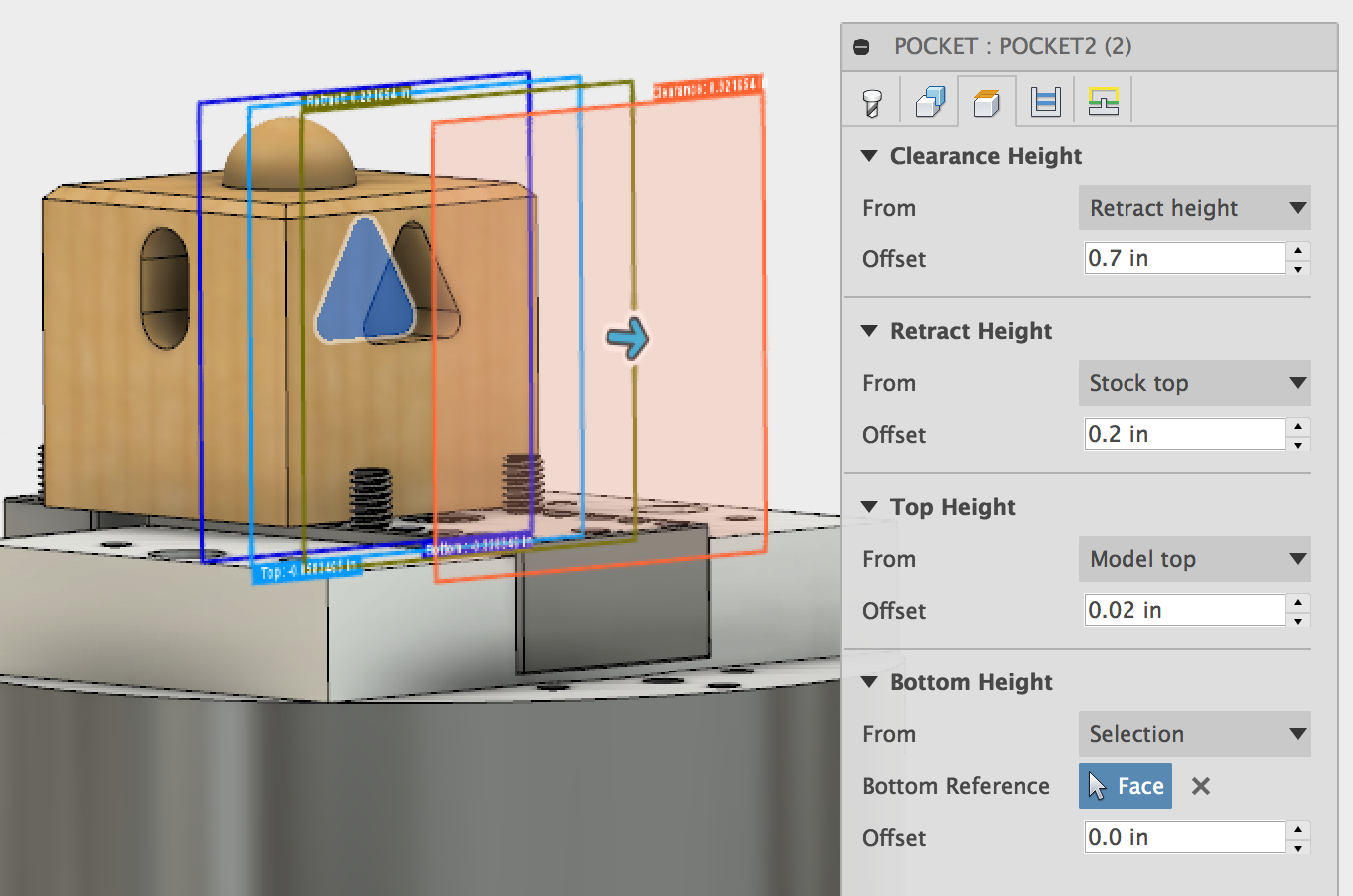
There are three changes that need to be made to the toolpath. First, the orientation of the toolpath must be updated, second, the bounding box for the toolpath needs to be updated, and finally the faces defining the toolpath heights need to be re-selected in the “Heights” tab. The settings in the “Tools,” “Passes,” and “Linking” tabs can be left alone.
The following screenshots show the changes that need to be made.
The orientation of the toolpath needs to be changed so that the Z axis points away from the face being machined and the Y axis points toward the top of the part.
Select the profile of the pockets to be machined as the machining boundary.
Finally, change the settings in the “Heights” tab to match the screenshots below.
Repeat these steps for the other both the triangular and square pockets of the part. Click “Ok” to save and apply the changes to the toolpaths.
When you are finished creating the pocketing toolpaths they should look similar to the pictures below. You can view more than one toolpath at once by holding down the “Ctrl” key while selecting them from the model tree. See section 9 for how to create G-code from your toolpaths.
...
...
Section 7: Radial Toolpath
A radial toolpath will be used to cut the hemispherical face on the top of the part. This path keeps the cutter in contact with the part and uses paths that are equally spaced radially around the selected centerpoint. This toolpath will follow the contour of the face in the Z direction with toolpaths spaced a constant radial distance away from one another on the hemispherical face.
...
The ⅛ inch single flute cutter will be used for this toolpath. This is tool 10 in the Pocket NC tool library. See section 3.1 for instructions on importing the Pocket NC tool library. See section 3.2.1 for instructions on how to select the tool for a toolpath. The speeds shown below work well for wax. They may have to be decreased for harder materials. Note that the lead in and ramp rates are very low. The way that this part is machined leaves a cusp above the hemispherical face. In order to avoid hitting at full speed, the ramping and lead-in feed rates are reduced.
...
Switch to the “Geometry” tab to select the portions of the model that will be machined with this path and to set the orientation of the toolpath. Start by orienting the toolpath so that it matches the picture below. Make sure that the origin is set to “Setup WCS origin.”
...
Select the bottom edge of the hemisphere as the machining boundary. Choose the centerpoint of the hemisphere as the center point of the toolpath by selecting the base of the hemisphere while the “center points” selection field is highlighted. Set the containment method to “Tool Outside Boundary” in order to ensure that the entire surface is machined. The “Slope” settings should be set to allow the toolpath to machine from an angle of 0 degrees to angle of 90 degrees.
...
Switch to the “Heights” tab. The only thing that needs to be changed is selecting the top face of the part as the bottom height for the toolpaths.
...
Under the “Passes” tab set the angular step size. This controls how close together the tool paths are. The closer these paths are to one another, the better the finish will be, but if they are farther apart the path will take less time. A step size of 3 degrees will work ok for this application, The larger the part is the closer together the toolpaths need to be.
The “Angle From and To” settings control whether the entire circumference of the surface will be machined. We want all of it so we want to go from 0 degrees to 360 degrees. The outer limit and minimum stepover can be left alone. We will allow the tool to cut both directions since we are prioritizing speed over surface finish.
...
The settings in the “Linking” tab can be left at the defaults.
...
When you are finished editing the toolpath, click “Ok” to close and save the toolpath settings. Fusion will calculate the toolpath. After the toolpath has been calculated it will display when you click on it in the model tree. It should look similar to this. Create G-code from your toolpath using the instructions in section 9.
...
...
Section 8: Multi-axis Swarf Toolpath
A swarf toolpath will be used to create the final feature on the part, the chamfered edge around the top. This toolpath is a multi-axis toolpath that will take advantage of the the Pocket NC’s 5 axes of movement to cut the geometry with the side of the tool rather than the tip.
...
Take extra care to make sure that your toolpath settings are correct when programming a 5-axis toolpath. It is much more difficult to visualize how the toolpath will translate into machine movement than it is with 3 axis paths. It is a good idea to check all of your paths by running them without a part installed and/or without a tool installed in the machine. This is particularly true of 5-axis toolpaths.
For this toolpath, the cutter is going to approach the part from the top, then the part will rotate so that the chamfered edge is cut around the perimeter.
The same tool used for the rest of the toolpaths will be used to cut the chamfer. The tool is tool 10 in the Pocket NC tool library, the ⅛ inch single flute cutter. See section 3.1 for instructions on importing the Pocket NC tool library. See section 3.2.1 for instructions on how to select the tool for a toolpath. The speeds shown below work well for wax. They may have to be decreased for harder materials.
...
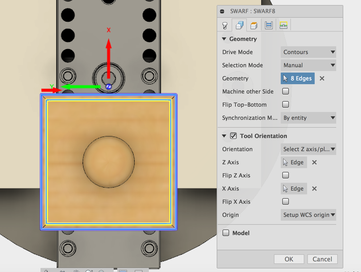
The geometry tab is where you pick which surfaces will be machined as well as setting the orientation of the toolpaths. Make sure that the origin of the toolpath is the Setup WCS origin. Select the orientation of the tool so that the coordinate system matches the picture below.
Select the geometry to be machined by choosing “Contours” as the drive mode, “Manual” as the selection mode, and select the top and bottom edges of the chamfer. The top edge should be yellow to indicate that it is the top profile. The bottom edge should be blue to indicate that it is the bottom profile. Use the “Flip Top-Bottom” button to flip the relationship of these edges if they are wrong.
...
The settings for the Heights tab are shown below. The bottom height is set using a -0.35 offset from the top face of the model.
...
The passes settings are shown below. The step down and stepovers shown are appropriate for soft materials such as wax. They would need to be decreased for harder materials.
...
The “Linking” tab settings are shown below. The default settings will work for this part. The only thing that has been changed is selecting where the toolpath will start and end. The default was to start and end on a corner. The start point was moved to the middle of one of the sides so that the tool ramps smoothly into the material.
...
See section 9 for instructions on how to create G-code from your toolpath.
...
Section 9: Post Processing
In order to create machinable code from the the toolpaths that have been created the code has to be post-processed into G-code. This is the process that Fusion’s software uses to transform the toolpaths into code that the Pocket NC can use.
The toolpaths may be post processed (“posted”) individually or several of them may be selected at once and post processed together. It may be helpful to post process your programs one toolpath at a time until you are confident that they are doing what you want them to do. It is much easier to troubleshoot smaller programs than large ones.
Once you are sure that they are working correctly, it will save time to group as many toolpaths together as possible by posting all of the paths that use the same tool and the same stock setup together.
Post process a single toolpath by clicking on it and then clicking “Actions” > “Post Process”. Alternatively, you may right-click on the toolpath and select “Post Process” from the menu.
...
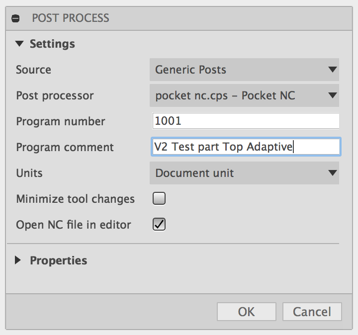
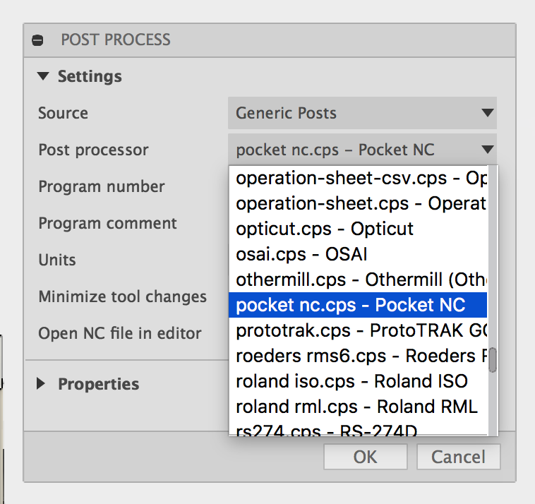
Once you click the “Post Process” button, a dialogue box will appear where you can choose which post processor to use and add comments to the code. You must select the “pocket nc.cps Pocket NC” post processor from the list. Every CNC machine has unique geometry, speeds, number of axes of motion, and other boundary conditions, so every machine has a slightly different post processor. The code will not work correctly on the Pocket NC mill if it is not written with the Pocket NC post processor.
Any comments that you add here will be added to the beginning of the code. They will not be executed by the machine. This is good place to record the part name, revision number, date, the code’s author etc. for future reference.
|
Once you have selected the correct post processor, click “ok.”
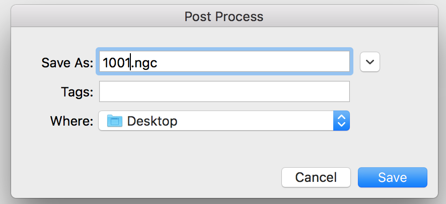
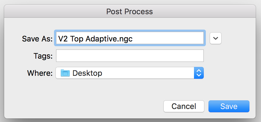
A second dialogue window will open asking you to name the program and specify where it will be saved. Give the program a descriptive name. The file extension should be left as .ngc. The file should be written to either a local file directory on your computer or a removable storage device such as a USB flash drive.
|
Click “Save” to post process the toolpath and write the G-code file to the specified location.
It is possible to post process more than one toolpath at once by selecting as many as desired using Ctrl + click then following the procedure described above.
Section 10: Setup and Running the Program
Section 10.1: Load the Tool
Use the ⅛ inch single flute cutter for this part. This tool is suitable for soft materials such as wood, wax and plastic.
Mount the tool in an extended tool holder. The tool stickout needs to be about 1.25 inches. Mount the tool in the machine and tighten the setscrews in the spindle.
Make sure that the collet nut is tightened and that the set screws are tight. Set the tool length offset for the tool for tool 10. See section 3 of the Software Overview tutorial for more information on how to set the tool length offset.
...
Section 10.2: Mount the Vise
See the workholding tutorial for more information on how to mount the vise on the machine.
Make sure that the vise it set up so that it matches the image below exactly. You may need to adjust the set screws.
...
Section 10.3: Mount the Stock
This part is designed to be cut out of a 2 x 2 x 2 cube of wax (pine pictured below).
Center the stock in the vise and tighten the 5 mm screw until the set screws start to bite into the part. Check that the workpiece is tight by trying to rock it back and forth in the vise.
...
Section 10.4: Load and Run the Program
Upload your machining file (G-code file) to the machine by clicking on the “Upload New File” button.
...
Select your .ngc file from the file directory on your computer or USB flash drive. Note that G-code files must be 2.5MB or less to transfer. This is also the maximum file size that the Pocket NCs’ processor can handle when it comes time to check the Gcode for errors before running it.
After the file has been successfully uploaded, the file name will appear in the file window in the upper left corner of the screen.
...
As well as in the bottom left corner of the screen.
...
Once the file is loaded, the code will also be displayed at the bottom of the screen under the “File” section. The user can view the code before running it and while it runs using this interface.
...
Run the program by clicking the green “Run From” button.
...
If you have a M0 or M1 command at the start of your code, the program will be paused. Click the blue Pause/Resume” button or push the green Pause/Go button on the machine in order to start the program. The user may pause the program at any point by clicking the “Pause” button or pushing the green button on the machine. The user can stop the program by clicking the “Stop” button or pushing the red, emergency stop button on the machine.
...
The user can change the feedrate and spindle speed while the program is running by toggling the Spindle Rate and Feed Rate controls. The arrows adjust the speed in 5% increments. The reset button resets the value of the spindle of feed rate to 100% of the program value.
...
